|
|
Case Study - Autonomous Vehicles© |
|---|
|
Case Study - Autonomous Vehicles
Introduction: This page is our Case Studies of Autonomous Vehicles (AV) and it is also part of our Virtual Edge Computing with Machine Learning as a replacement of Edge Computing Boxes-System. Based on whom you talk to, AV is either a total success or another failure. Our answer is: so far, we do see plenty of electric cars on the roads, but hardly we see Autonomous Vehicles (AV) driving on roads with no driver on broad. Therefore, success or failure is not part of this page's goals. Letter to The Department of Defense (DoD) and The Air Force is Our Main Target: Our Autonomous Vehicle (AV) analysis and architect is an intelligent Virtual Automated Integrated System which would be the seed for something bigger such as Autonomous Fighter Jets, Tanks and other DoD hardware. What we are presenting is not a trial and error system as most AV vendors are running into, but our AV is true system which addresses all the hardware (bare-metal) and software. By searching the internet, sadly most AV vendors' claims seem to be more marketing since we do not see any mass production of their AV running on the roads for the world to use. Compression-Encryption System: Part of our Cybersecurity architects, tools and approaches and products would be using our Compression-Encryption System. Our Compression-Encryption System in a game changer in data streaming, Compression-Encryption and Cybersecurity. Our Focus: Our focus is using virtualization, intelligence, automation, cloud, Cybersecurity, integration, Machine Learning and DevOps and DataOps to structure an intelligent dynamic robust solution to Autonomous Vehicles. As for Hardware, our DevOps is our only focus and not the AV mechanical parts nor AV's sensors. We view them as data sources. Main Issues and Our Goals: Our AV page is to present issues and goals and not to debate on AV issues. We would look at any AV as we would be looking at cloud networks and Data Centers. The main issue of AV is that AV is a dynamic system with continuous generation of non-structured terabytes of data which we would need to store, analyze, process, and use to make decisions and give choices. Our Goals in this page are covering the following: • Analysis and View - See Something Through a Different Lens • Components and Machine Learning • Structure • Interfaces Communication • Data • Intelligence • Security • Processes • Machine Learning • Management • Possible Solutions • Autonomous View • Using Computer Models and Virtual Testing Analysis and View - See Something Through a Different Lens: We recommend that the readers check the following pages as quick references to our first part of AV's analysis. Electric Vehicles© Virtual Edge Computing with Machine Learning© Our AV case study is based on electric vehicle and our Case Study - Electric Vehicles (using 2022 Tesla Model Y as our electric vehicle Case Study) is our starting analysis of our AV case study. Views (See Something Through a Different Lens): Einstein demonstrated to us in the early twentieth century that if we look at anything through a different lens, what we perceive will be different. The following are how we would be viewing the same thing: • Closed Box View • Virtual Container and Virtual Components View • Autonomous Vehicle Components' Functionalities View • Interfaces View • Data Flow View • Processes View • Time View • Cloud View • Security View • Machine Learning View • Using Computer Models and Virtual Testing Closed Box View: 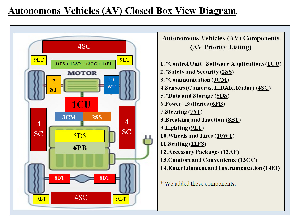
Image #1 Image #1 is our Closed Box View, which means we would be looking at each item within the image as a closed box with no details. Based on our research of most popular AV and our Electric Car Case Study (2022 Tesla Model Y features Car Features), we came up with the components in Image #1 as closed boxes. We used Tesla car features s part of our analysis. We set their priorities, names and locations as we see them. We also added other boxes such as Control Unit - Software Applications (1CU), Safety and Security (2SS), Communication (3CM) and Data and Storage (5DS). We renamed them according to their ranking priorities and name abbreviation. For example: 1CU = priority #1 and name is "Control Unit which is composed of Software applications" 5DS = priority #5 and name is "Data and Storage" We believe "Closed Box Approach" makes it easier for people to see the overall picture without any overwhelming details. As for AV sensors "Sensors (Cameras, LiDAR, Radar) (4SC)" and their locations, we placed them within one closed box type (4SC). There are more than one 4SC boxes. As for the feature 11 though 14, we boxed them together since their priorities is lower than other features. * is an indication that such a component or closed box is our addition and not necessary AV component. Virtual Container and Virtual Components View Quick Definition: What is Virtualization? Virtualization or virtual system is a simple and a powerful concept. Virtual means it only exists in a computer memory. All programs, images, sounds .. etc are virtual objects. Turning off a computer would results in the loss all the memory contents which are the virtual objects. To bring any virtual object back, it has to be loaded back into the computer memory. Virtual Container and Virtual Component: We call each Independent Virtual Sever a "Virtual Container", since it has its own operation system (OS) and all the supporting system software to run as a cloud virtual server. A "Virtual Component" is an application or a cloud application which runs within a Virtual Container. One Virtual Container may have one or more Virtual Components running within the Virtual Container. Our architect use Virtualization and we are presenting four different types of Virtual Containers and Components. Each type has features which would help in optimizing the virtual implementation. Our four Virtual Types are as follows: • Virtual Container (Server) with One Dedicated Application (Component) - no sharing of resources • Virtual Container (Server) with Multiple Applications (Component) - sharing resources with different applications • Virtual Container (Server) with Machine Learning Support - only one Supporting application and Machine Learning tools • Control Unit Containers - a physical server (bare-metal) with virtual containers and components Virtual Container (Server) with One Dedicated Application 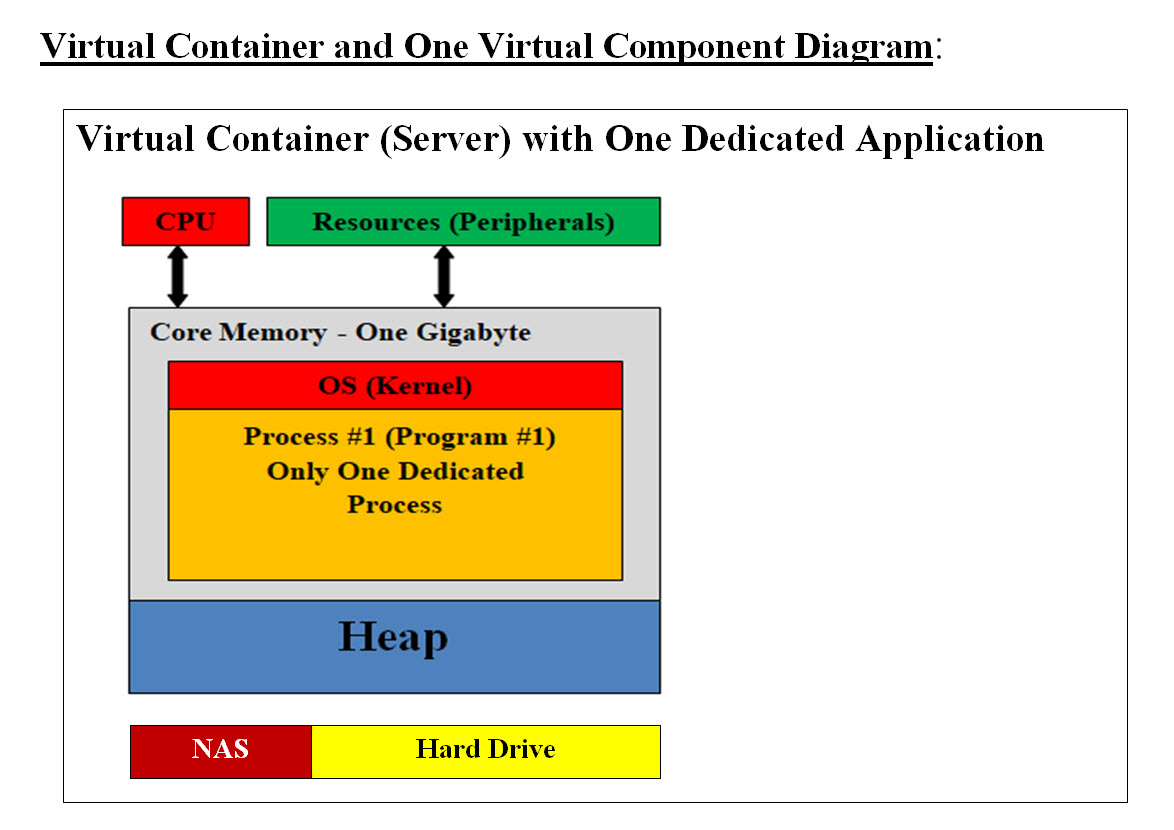
Image #2 In Image #2, we are presenting a Virtual Server or a Conatiner. We are showing the core memory content of each computer. In a nutshell, all programs including the operation system are running memory. CPU executes each process (commands-programs). These programs communicating with peripheral (IO devices). Turning off any of these computers would results in the total loss of every virtual object loaded in memory. When and Why would we need such a Virtual Container (Server) with One Dedicated Application (Component) - no sharing of resources? This would boost performance and no possible interference nor possible hackers' code. There is only task such system would be performing. For example, reading and writing to a storage device. Heap: Heap is a region in the computer main memory used for dynamic memory allocation. Memory Heap is a location in memory where memory may be allocated at random access. Most programs including the operating system use Heap to dynamically get extra memory. What is a virtual system? By defining the difference between Physical component and Virtual component, we would be defining virtual system. Physical Components: Physical components are the actual hardware components such as core memory, hard disk, Bare-Metal server, routers, CPU, NAS and network connections. Virtual Components: Virtual components are running programs (such as OS), images, virtual server, virtual routers, virtual networks Physical Server: A physical server is also a computer with CPU(s), memory, operating system, peripheral but it would have additional features to communicate with internet or other networks. It is also known as Bare-Metal. Virtual Server - Virtual Container or Container: A virtual server or a Container is a group of software programs working together to mimic the functionality of a physical dedicated server. It is also called a Virtual Machine. Each virtual machine can run its own operating system and applications and act the same as a unique physical device. We need to emphasize that a Virtual Server only exists in memory. The Size of Core Memory: What is meant by diminishing return? The law of diminishing returns is an economic principle stating that as investment in a particular area increases, the rate of profit from that investment, after a certain point, cannot continue to increase if other variables remain at a constant. The size of a Virtual Machine in bytes is critical to its performance. The bigger the size the more space to run software, but the law of diminishing return plus the resources available would help in defining the size of a Virtual Server. Storage - Network Attached Storage (NAS) and Hard Drive These are support physical storage - permanent memory Virtual Container (Server) with Multiple Applications (Component) 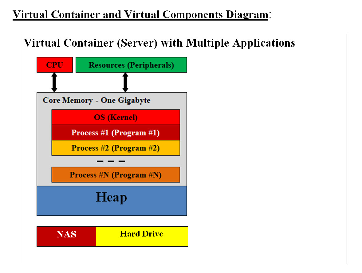
Image #3 Images #3 is showing Virtual Container (Server) with Multiple Applications (Components). One Virtual Container with N number of Components (applications) sharing resources. This is the most common Virtual Container. Virtual Container (Server) with Machine Learning Support - Supporting application and Machine Learning tools 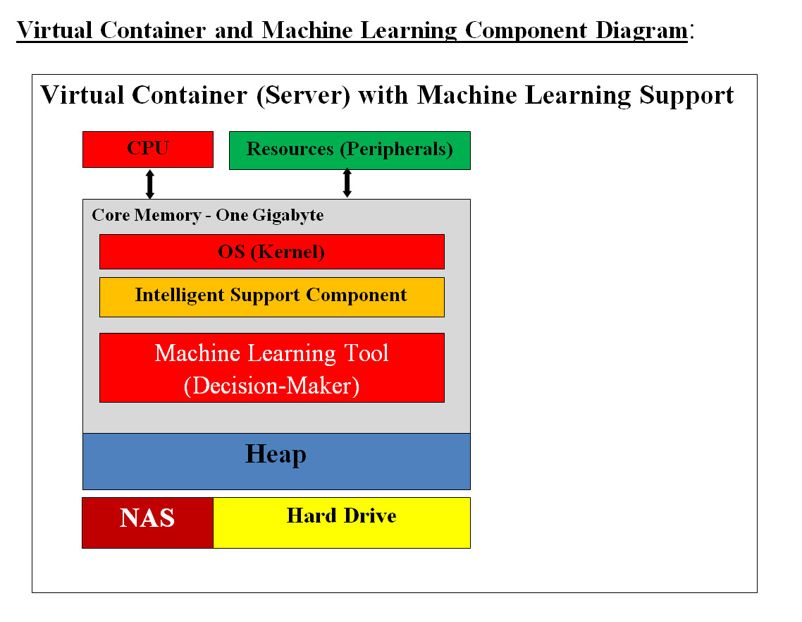
Image #4 Image #4 shows a Virtual Container (Server) with Machine Learning Support, which has two major Virtual components: • Intelligent Support Component • Machine Learning Tools - Decision-maker Intelligent Support Component: In the case where any component runs into a situation which requires intelligent decision making, then the Intelligent Support Component or application would called to handle any issues. For example, the security component would be performing detection, scanning and Push-Poll of each AV's components. let us say that if one of the sensor would not respond to Push-Poll request, then the security component will communicate with the Control Unit, create Virtual Container (Server) with Machine Learning Support. Such a Virtual Server with sensor Intelligent Support Component and Machine Learning would spring into action to handle the sensor's situation. Machine Learning Tools - Decision-maker: For sensor's failure example, Machine Learning Tools would have history of all previous issues or possible issue and would provide the Intelligent support with a check list and a matrix with function calls and exception handling to remedy the case. The Machine Learning Tools would audit trail the case and all data associated with the case and send them to the cloud for analysis and future solutions. We are proposing in our architect that each AV's component such as Battery (6PB) must have an independent supporting decision-making application to handle issues plus Machine Leaning tools to help the supporting decision-making application. Both the supporting decision-making application and Machine Leaning tools are not part of AV's components, but are a service to AV's components and they would be activated to help with decision-making. For example, if the battery charge sensors reach the recharge warning and the battery needs to be recharged, then the support-decision-making application would be activated by creating Virtual Container (Server) with Machine Learning Support. The Intelligent Support Component or application would start the following: • Check the warning • Communicate with Control Unit to perform the needed task • Communicate to AV's electric motor to use more economic electric motor use • Using navigation and Machine Learning Tools to figure out the closest charging station • Staring Navigating the vehicle to the charging station Both the supporting decision-making application and Machine Leaning tools have their own Container to run within and not to load the battery component's processes. One of the Machine Learning task would be sending the performance and audit trail data to the cloud for audit trial and further analysis. Control Unit Containers 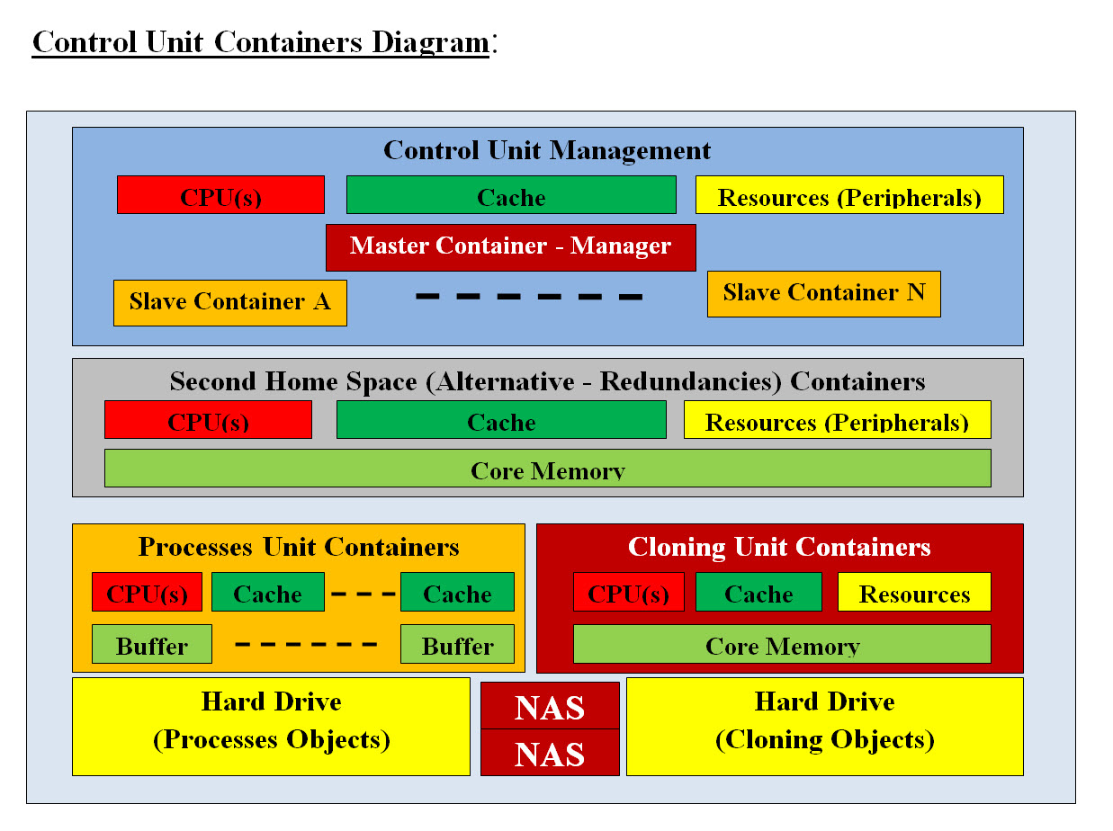
Image #5 Image #5 presents our Control Unit in term of software and hardware. Time Element: Vehicles which run themselves (Autonomous Vehicles(AV)) would be running on the road where a split of a second would result in a disaster. The Time Element is very critical in the AV's performance. There is no room for errors. Plus there could be an infinite number of possible situations where AV may or not may have the handling. Therefore, our architect should not have any performance issues, internal problems nor lack of communication. AV performance could not afford to have its brain or its command center be the only control of the AV. AV's component cannot afford to have some other components' problems, issues, nor its previous runs dangling code or data. Our architect has each AV's component run as a solo system which is reloaded on regular basis, with communication and decision making support. Low Level Code: Due to the time restrains and speed of processes analyzing huge heterogeneous data (radar, laser, sound, camera), we might be forced to use low-level code such as C in the developing of some modules. Dual Control: Our architect's goal when it comes to control, that there should be two control systems as follows: Each AV's Component Control: Each component would have the ability to start a new "check me out" - Virtual Container (Server) with Machine Learning Support to help figure out and correct any issues. Control Unit - Control In case of an AV component fails in the Push-Poll respond, then Control Unit would create "help the component" Virtual Container (Server) with Machine Learning Support to check the component with the option of creating a new Virtual server for replacing the failed component. Our architect's main goal is that each of the AV's component run independently. Each component would run solo without any concerns about the rest of AV's components. Even AV's communication would be a service. Handling issues would be done by decision-making application and Machine Leaning tools. This would help the components processing speed and handling. The only concern would be to run your dedicated tasks. For example, each camera would have only one job which is populating the video screens or frames with pixels where another component would do the processing of screen or the frame. For AV as system to run it must have: • Management system • Communicate with AV's components • Tracking - Push-Poll • Audit trail • Handle component crash or issues • An alternative space to run in case the software of the AV's component is damaged or has issues • Rollbacks • Refresh or reload - which would wipe all the previous run execution trash, data, bugs, hacker's code, ..etc • Data storage Image #5 is our Control Unit architect including the bare-metal. It is composed of three separate units. Each Unit runs independently plus permanent storage. It consists of the following: • Control Unit Management • Second Home Space or Alternative Virtual Component (Redundancies) Containers • Processes Unit Containers • Processes Hard Drive • Cloning Unit Containers • Cloning Objects Hard Drive • NAS For more details, see Autonomous Vehicle Components' Functionalities View section. Autonomous Vehicle Components' Functionalities View: We are presenting the functionalities of each component and our goal is to make it simple and not an overkill of details. 1. Control Unit - Software Applications (1CU) The Control Unit would be composed of a number Virtual Servers (Containers) with a Master and Slaves. A Master Server would manage and run the Control Unit. Slave Container would have only one task to perform. A Slave Virtual Server has the ability to move up in rank from Slave-Server to Master-Server and take control of the Control Unit. Once the virtual server is done with its tasks, it would be deleted totally from memory and that would free resources. A Master Sever would also be deleted-loaded on regular basis in case it has hackers' code. Our architect should be scalable both vertically by having more applications running within the virtual server and horizontally by adding more virtual servers as needed. The Control Unit would run only the needed applications and not be overloaded with idle applications. This also may help the Control United from being hacked or has hackers code or hacked applications. Second Home Space or Alternative Virtual Component (Redundancies) Containers: The Control Unit should have enough bare-metal support to run other applications as Second Home, or Alternative Virtual Container. Cloning these Virtual Container can also be used. Saving Clone Objects on the Hard drive can help speed the cloning processes. For example, if Steering Virtual Server (which is a container) with its applications (components) failed, then the Control Unit would create a new steering container with its components applications in the Control Unit bar-metal server and connect to steering hardware or parts and keep the steering functioning as it should. There should be a steering clone object (Container and its Components) stored on the hard drive which would be loaded using the Control Unit Cache and to clone the steering container and its components. Processes Unit Containers: For more details see Processes View section. Cloning Unit Containers: A Virtual Machine can be copied to hard drive as an image file. Copying the virtual machine is the most efficient way of backing it up. You can also copy the virtual machine, in case you want to image or clone it. Therefore, we recommend that most if not all the Virtual Containers and Virtual Components would created and test outside AV and once they are approved, then they would be cloned as VM images and copy to the hard drive. This would speed the loading and reloading of Virtual Containers and Virtual Components on the running AV. Clone Objects: We recommend that Virtual Containers and Virtual Components saved on the hard drive would be called: • "Container Clone Objects" • "Component Clone Objects" NAS: What is network-attached storage (NAS)? Network-attached storage (NAS) is dedicated file storage that enables multiple users and heterogeneous client devices to retrieve data from centralized disk capacity. NAS devices are flexible and scale out, meaning that as you need additional storage, you can add to what you have. The goal of having NAS is to provide storage to have a hardcopy of anything important happening in and around AV. NAS would help in rollback and audit trail. Processes Hard Drive: For more details see Processes View section. Cloning Objects Hard Drive: The main goal of having hard drive(s) is as a fast storage and they would be used in installing Clone Objects (Virtual Containers and Virtual Components). Cache Memory: Cache memory is an extremely fast memory type that acts as a buffer between RAM and the CPU. It holds frequently requested data and instructions so that they are immediately available to the CPU when needed. Cache memory is used to reduce the average time to access data from the Main memory Preloaded Clone Objects in Cache should be done based on system-AV statistics and frequencies usage and importance. This would help speed the loading and reload Clone Objects. 2.Safety and Security (2SS) Safety: For Safety we need more time to research what is needed. Security: Security would be performed by detection, scanning and Push-Poll of each AV's components. Security reports would be generated and send to the cloud for tracking and updated. Continuous cloud updates would be done for the detections. Logging and tracking AV location and AV components would be done for performance and tracking. Push-Poll reports would be created for all the AV components. These reports would also be sent to the cloud for evaluation of performance and detections. Note: Every application would have Push-Poll functions call for speeding the Push-Poll processes. On_AV and Off_AV Processes: Analysis, processes, detection, storage, ..etc would require time, resources and execution. Therefore, not all processes would be done in AV's bare-metal, but only the critical ones (On_AV) and the rest are send to the cloud (Off_AV) for processing and updates. Machine Learning Support: Machine Learning Tools are critical as background support and decision-making. See Machine Learning View section. 3.Communication (3CM) Both AV internal and external communication would a service performed by 3CM Virtual Servers for helping each components and not to be bogged down with communication of different protocols, sensors or changing technologies. This would help in changing communication protocols in case of the AV sensors are being damaged, targeted by hackers or thieves. For example, if 2SS detected an interference with one the sensor, then the sensor would switch to different communication protocols or signals (different frequency, band, .. etc) by simply make change request to 3CM. 3CM should be intelligent to handling issues without bugging down any of AV components. 4.Sensors (Cameras, LiDAR, Radar) (4SC) Sensors, navigation, tracking and detecting are eyes and ears of the system, plus Machine Learning support would help with decision making. Machine Learning would be used to eliminate duplicate and redundant data. Issues with Sensors: First we need to look at Image #6: JUN 16, 2020 10:07 AM Autopilot Blamed for Tesla’s Crash Into Overturned Truck 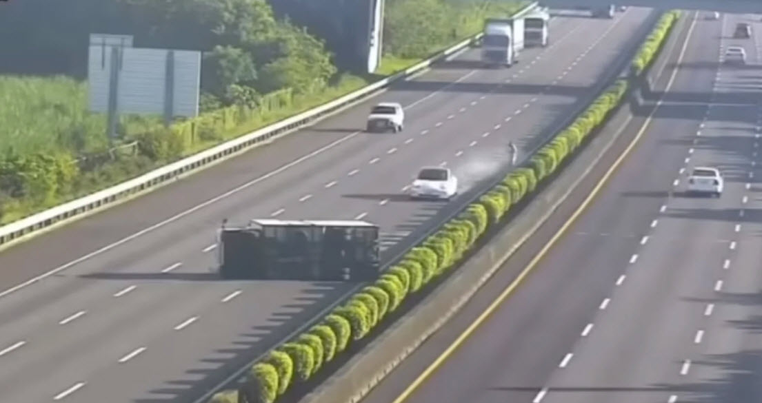
Image #6 This and other examples are incidents where Tesla vehicles struck several stationary police cruisers and even a motionless fire truck. There is a lot of speculation of why autopilot failed, but our analysis shows that motionless objects as the Overturned Truck or stationary or motionless highway signs are not seen by the sensors nor accounted for. Types of Sensors Currently Used: Autonomous sensors play an essential role in autonomous vehicles. These sensors allow cars to monitor their surroundings, detect oncoming obstacles, and safely plan their paths. The following are types of Autonomous sensors: Ultra-sonic: An ultrasonic sensor is an electronic device that measures the distance of a target object by emitting ultrasonic sound waves, and converts the reflected sound into an electrical signal. Ultrasonic waves travel faster than the speed of audible sound plus such sound humans can hear. Radar: Radar sensors are conversion devices that transform microwave echo signals into electrical signals. They use wireless sensing technology for detecting motion of objects and figuring out the object's position, shape, motion characteristics, and motion trajectory. Light Detection and Ranging - LiDAR LiDAR stands for “Light Detection and Ranging” and its technology allows self-driving vehicles to make calculated decisions with its ability to detect objects in its immediate environment. It can be thought of as a vehicle's “set of eyes” and the most important component in making self-driving vehicles a reality. Cameras: Cameras are image sensors and can automatically detect objects, classify them, and determine the distances between them and the vehicle. For example, the cameras can easily identify other cars, pedestrians, cyclists, traffic signs and signals, road markings, bridges, and guardrails Our Recommendation to Additional Sensors: We would like to stress the importance of sensors and we recommend that each sensor would running independently as a Virtual Sever or a bare-metal server. The existing AV sensors such as Ultra-sonic, Radar, Light Detection and Ranging - LiDAR and cameras may not be able to cover all possible detection or they would be overwhelmed with too many critical tasks. Therefore we recommend additional independent sensors as follows: 1. Traffic Light Sensors 2. Local Area Network Sensors 3. Intersections 4. Mapping Sensors 5. Road Sign Sensors Traffic Light Sensors: We recommend that there should be a Traffic Light Sensor, which would have only one task and that is handling Traffic Light Signals. The Traffic Light Sensor would be designed (if possible) to communicate with traffic lights by receiving coded signals, the same way Fire trucks communicate with traffic lights. It would also be able to read Traffic lights signals with or without communication and specially pedestrians signals. Local Area Network Sensors: These sensors would be a part of the cloud communication. Issues which other AV encountered, these issues would be sent to the cloud, analyzed and sent to other AVs to use in their navigation and handling these issues. Security or Cybersecurity is the center of such communication. Hackers can use devices such as drones which would be intercepting and sending wrong signals to cause issues. Intersections: The same concept as the Local Area Network Sensors would be used. We need to give more attention to intersections where most accidents would occur. Mapping Sensors: For AV to be able to build a map of its surrounding and possible issues, we recommend that Machine Learning, Cloud analysis, navigation and other sensors to be used to build a map of the surrounding Road Sign Sensors: Note: Braille People read Braille by moving their fingertips from left to right across the lines of dots. Developed in the early 1800s by Louis Braille, Braille is a series of characters, or "cells," that are made up of six raised dot patterns, arranged in a rectangle containing two columns of three dots each. Road Signs would be using pattern of reflecting dots which can be recognized by AVs Road Signs Sensors even in the dark. We would also recommend that road signs would be communicating with Road Sign Sensors. Road signs with highway names and numbers can also be using Braille methods of reflecting dots. We are not neglecting navigation, but we are adding more detection and analysis options to AV. At this point in architect stage, our handling of sensors is: We treat them as a closed boxes which generate data and the data would be parsed, stored and sent it to the cloud for further analysis. The Push-Poll of each sensor would be also performed for security and creating Components Push-Poll reports. Sensors' Management: Sensors type and location within the AV would require a management system. At this point our Sensors' Management is a Closed Box. Robust Virtual Sensors: At this point in the architect, the physical components of AV's sensors need to addressed by other teams and their support. As for the sensors' software, we recommend that each sensor would be running as an independent Virtual system. There should be options of rebooting from the data hard drive. We also recommend that the virtual system would stored as a clone object (Image File), and rebooting would be just a memory copying from the disk. Cache memory would be an added boost to such a processes. 5.Data and Storage (5DS) Our approaches to data and storage is that we do not treat data and storage as dummy objects. They should be virtual services scalable vertically and horizontally. Such services should have their own processors, processes, Cache, memory and run as an independent intelligent system. Data: Our Architect and AV Data: The main issue of AV is that AV is a dynamic system with continuous generation of non-structured terabytes of data which we would need to store, analyze, process, and use to make decisions and give choices. Therefore, Data and Processing the data is our architect plus AV runs on data. AV relies entirely on the data they received from GPS, radar and sensor technology, plus the processing of data from cameras. Every AV component produces data which must be stored, analyzed, used with decision making plus data would be sent to cloud for further analysis and Machine Learning. Sensor's Data and Our View Frames: Different sensors see or view the would differently. How do sensors (Ultra-sonic, Radar, Light Detection and Ranging (LiDAR), Cameras or any sensor) view the world around them? What is our Digital View Frame? Each of Av sensors produces Hugh amount of different types of data which must be analyzed, processed and used with decision making. Regardless of the type the data produced, these data must be converted into one type format for analysis. We believe that sensors' data must be converted into Digital View Frames. 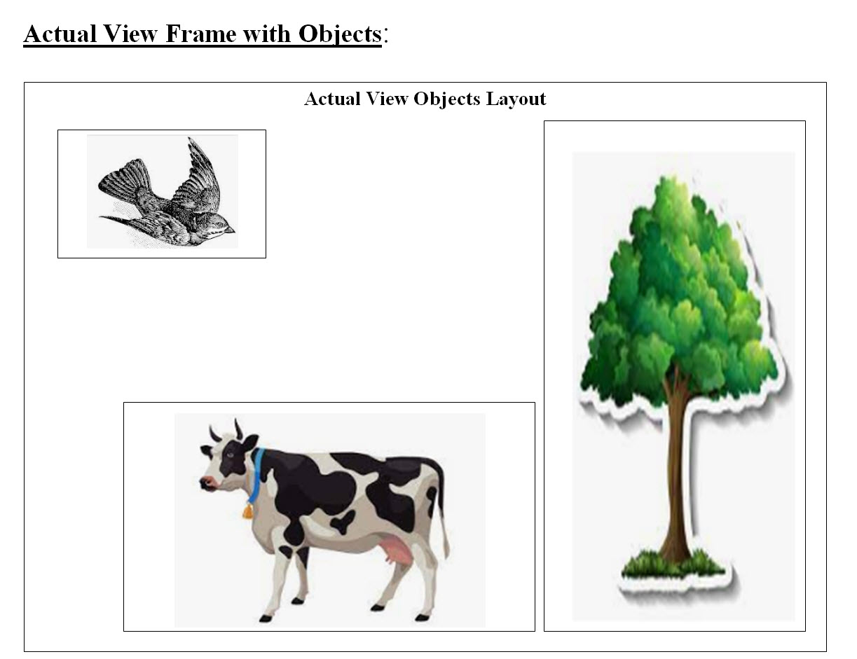
Image #7 Image #7 is rough representation of possible objects found on the roads. Each AV sensor would produce a Digital View Frame based on their technologies. Our Digital View Frame: Our approach to how AV see the road and what is running in it or associated with it is through digital frames. Our Digital Frame is nothing but a computer screen or a memory page or a table swith equences of bytes or bits.
For us human to be able to view a memory segment, a page or table, we would see memory segment better if we view it as a table of rows and columns. Table #1 is a rough presentation of our View Frame as an array of sequence bytes. Why view as Bits? Note that one byte is equal to 8 bits so it is quite hard to see memory as a sequence of bits, but for processing speed, Bit comparison is done on the hardware level and it is extremely fast. The number of possible Digital View Frames and their contents: • Ultra-sonic • Radar • Light Detection Ranging (LiDAR) • Cameras • Other sensor Sub Frames: A screen frame's size which would cover the AV view of the road and what is in it, can be Hugh. Analysis of such Hugh frame may take time where time is a big factor of crashing or not crashing into an object. We are proposing that a View Frame should be divided into equal size of sub-frames. The position of the sub-frame has priority in our analysis sequence. This means the first sub-frame which we would start our analysis may depends on which sub-frame has the most damage in case of a crash. Image #8 has our view of our View Frames, Sub-Frames and their processing sequence priority numbers. 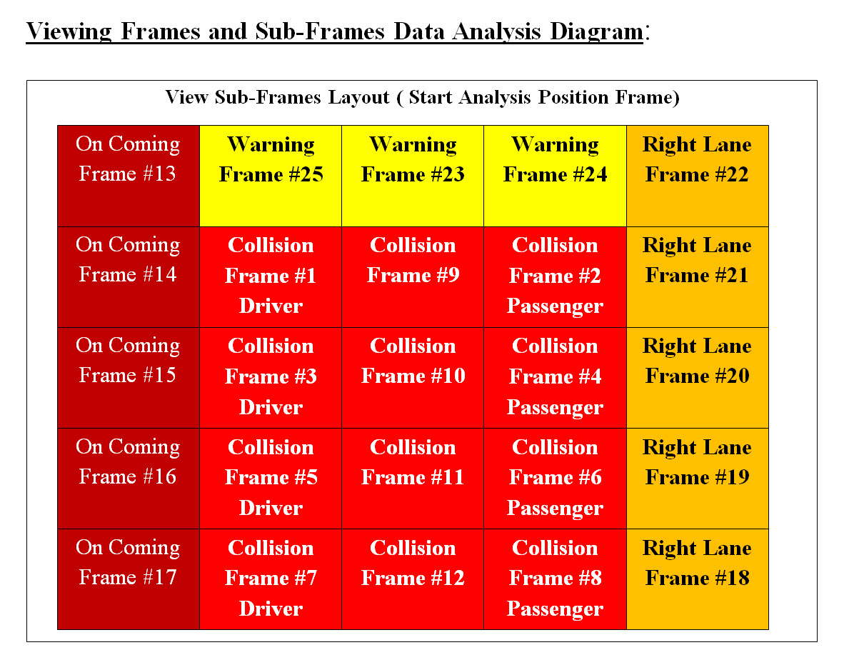
Image #8 Image #8 is showing our View Frame with sub-frames. We are building an autonomous vehicle which drives itself. We also looking at the worst case scenario sub-frames. Assuming that there are a driver and a passenger not wearing their seatbelts setting in the car, then Sub-Frame #1 and #2 should have the highest priority in our sub-frame analysis. Therefore, if Sub-Frame #1 and #2 have possible crash or impact, then AV should have to perform the crash prevention processes and no further analysis is needed. The rest of sub-frames analysis would be moved to Machine Leaning processes and track history. Our View Frame Building: We are proposing that every senor would build sequences of digital view frames. Therefore, Ultra-sonic, Radar, Light Detection and Ranging (LiDAR), Cameras or any sensor must build digital view frames based on each technologies used. Each view frame would capture the AV's view in time. Each view frame would have a timestamp-distance presenting the time and distance from the AV. Each view frame would be analyzed according to sub-frame analysis sequence we presented in Image #8. 
Image #9 
Image #10 Processing Sub-Frames Verse Time We may have four or more different types of View Frames (Ultra-sonic, Radar, Light Detection and Ranging (LiDAR), Cameras or any sensor). Each View Frame would be processed independently and the outcome of each process would be used to make a decision. Based on a preset conditions and rules (which we would explore later), AV would start a series of actions or processes. 
Image #11 Looking at Image #11, we see that Sub-Frame #2 through #8, there would be a possible impact or crash. Our Analysis would stop at Sub-Frame #2 and no further analysis would be required to start crash prevention processes. At the same time, the entire View Frame would be moved to further analysis by Machine Learning and send to the cloud. The total analysis time saved by stopping the analysis at Sun-Frame #2 would help speed the processing and Machine Learning would be performing the entire View Frame analysis. Note: The analysis of each type of View Frame (Ultra-sonic, Radar, Light Detection and Ranging (LiDAR), Cameras or any sensor) must follow the sub-frame sequence and provide the analysis to increase the actual processed and decision making. Different View Frame with Sub-Frames for Different Roads: Road types and conditions are not the same, therefore the View Frame with Sub-Frames in Image #8 may have different analysis sequences. For example, driving on a mount road with possible falling rocks, would require a different View Frame with different Sub-Frames analysis sequences. The same goes for city driving with pedestrians. Sensors' Frame Analysis Time, Stopping Distance and Buffer-Cushion Delta Time: Delta Definition: Mathematics: an increment of a variable Business: a risk metric that estimates the change in price of a derivative. Delta Time: Delta time describes the time difference between the previous frame that was drawn and the current frame. Before, we start analysis of Delta Time, we need to look at what a human driver would normally do in the case of possible crash? We are using a semi truck weighs around 80,000 pounds traveling at a speed of 65 miles per hour - see Image #12 and Table #2. We are presenting time and distance for a semi truck weighs around 80,000 pounds traveling at a speed of 65 miles per hour:
Table #2 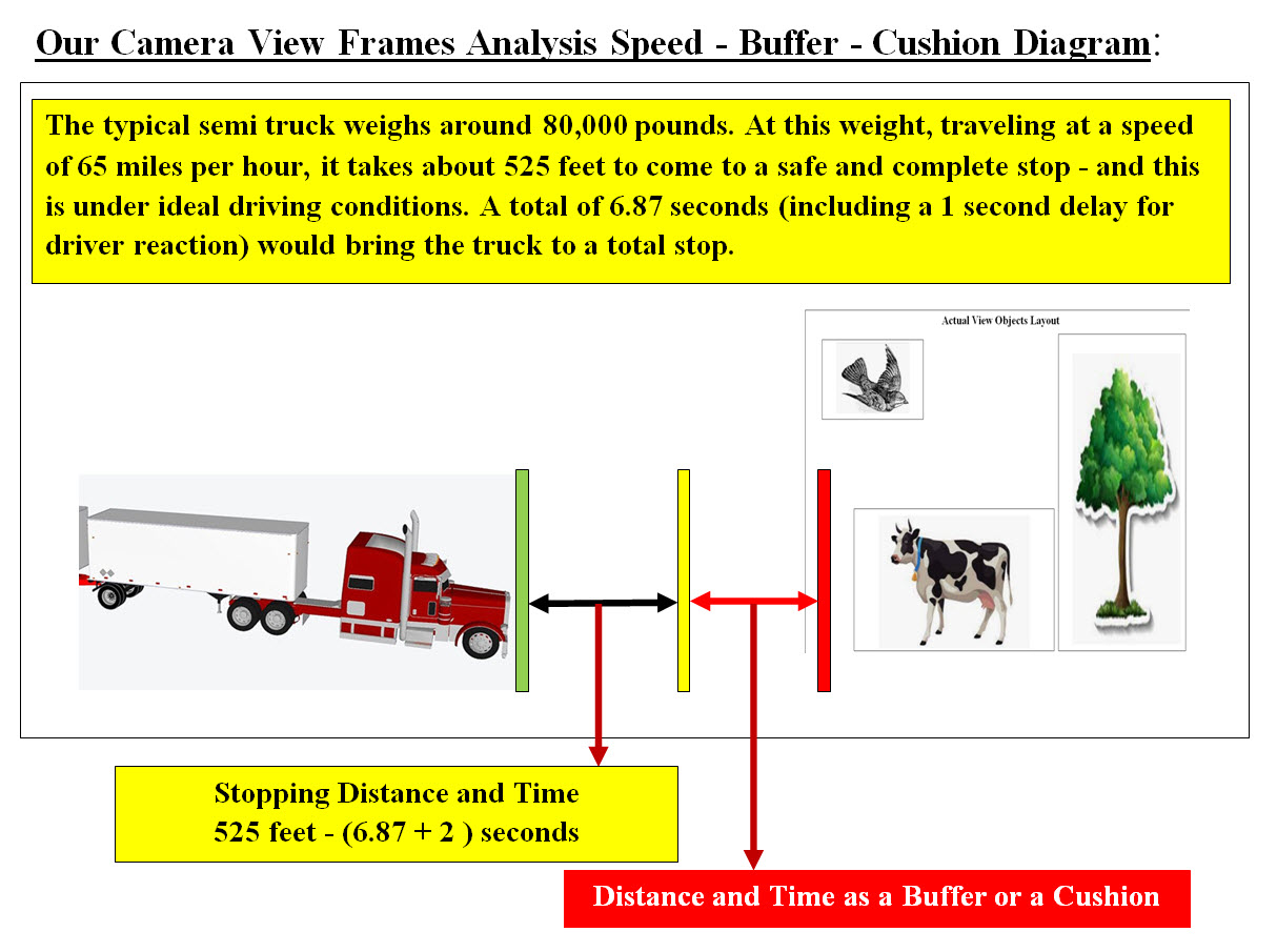
Image #12 Table #2 and Image #12 represent our View Frame Analysis approach using the semi truck in our illustration. Notes: We can see from Table #2 that we may have 2 seconds and 525 feet to bring an 80,000 pound semi truck to a complete stop. How far the View Frame Should be from the vehicle front side? Image #12 gives a rough estimate of how far should the crash View Frame be? Stopping Distance: The distance is a factor of the speed of the vehicle. The slower the vehicle speed the less distance required to bring the vehicle to a complete stop. View Frame Processing Speed: As for the Viewing Frame Processing, we would use worst case scenario which translates to less processing time, which would be less than 2 second. Buffer-Cushion The Buffer or Cushion is the distance between the stopping point and possible crash point. How big of a distance-time the Buffer-Cushion should be is dependent on the following: • Vehicle speed • Vehicle weight • The speed of vehicle computing analysis • The size and type of the data being analyzed • Road type • Road condition • Weather • The Possible crash and the surroundings objects • Misc - any possible objects or condition we did not include What else would we do with data? AV relies entirely on the data they received from GPS, radar and sensor technology, plus the processing of data from cameras. Our architect would address the following later with other sections: • Types • Size • Processing • Conversion • Compression and Encryption • Security • Eliminating redundancies • Cloud exchange • Control Unit Containers AV Camera Processes Factors - Frame and Sub-Frame Analysis: The following are more of brainstorming of how to process AV's camera frames and sub-frames: 1. High-speed video cameras that record up to 120 frames or photos per second generate gigabytes of video data 2. Number of frames are created by the camera X time 3. The number and the size of each frame 4. The time it takes for image to be processed 5. The Distance between AV and Object - plus vehicle's and the object(s) speed and directions 6. Sub-frame and the object(s) location 7. Direction of object moving - coming, going, crossing, flying, ..etc 8. The speed of object motion 9. The difference between the frames FrameT1, FrameT2, Frame-Crash 10. The time needed to start crash-voidance processes 11. Is it faster to compare frames (Bit comparison) or analyze frames 12. Processing approaches of Objects within a frame: a. Knowing Object b. Unknown Object 13. Parallel processing Storage - Critical Component: How critical is the data storage in AV processing, security and Machine Learning? Our architect is handling AV as a Big Data project. To our architect, we are handling AV components as data sources which must be analyzed, processed, secured, stored and send to the cloud. Our Machine Learning would process the new generated data as well as send data to the cloud for further analysis. Every AV component would be hardwired to the AV Data Storage (5DS). Plus every AV component would have more than one connection to AV data Storage (5DS). The redundancies are designed to help in keeping the data connection available in case of malfunction of AV components or crash damages. Data Format, Size, Processing, Storage and Copied to Cloud: Autonomous Vehicles (AV) Components Interfaces: The goal is to have distributed processes with Central management. Each component runs on its own bare-metal. Each component should be a totally independent unit which is hardwired to the Control Unit (1CU) , Communication Unit (3CM) and Data Storage (5DS). Each component would run independently under the Control Unit (1CU) managements and commands. It would be sharing storage and Data Storage (5DS) with other components. As for the questions of size of such a bare-mental. Each component (other than 1CU, 3CM and 5DS) would be as simple as a small motherboard with its own processors, cache, core, IO connections (based on its services). With today's technologies a small size of a bare-metal server is doable. For power supply, connections, ventilation and required devices, we would need bare-metal vendors to support our requirements. Image #13 is a Google search for " small motherboard with its own processors, cache, core. .. etc". Each component would run using Virtual Servers which are created by the control Unit command. The hardwiring with the Control Unit would be used to create the components virtual servers. These virtual server would be stored as file image(s) on the Control Unit hard drive and Data Storage bare-metal servers. The Control Unit Cloning Unit Containers would be creating the components' virtual servers. 
Image #13 The following table is a quick representation AV components interfaces plus comments to how these interfaces are doable and with great interfaces' flexibilities.
Data Flow View: AV relies entirely on the data they received from GPS and sensors technology, therefore Data Flow View is critical since data is received and generated by AV's components. The amount of data running throughout AV components can be Terabytes of data. We need to set our focus on the view frames data generated by each sensor. We also need to mention that every sensor's data would be converted into Digital View Frames, which would unify the AV's analysis. 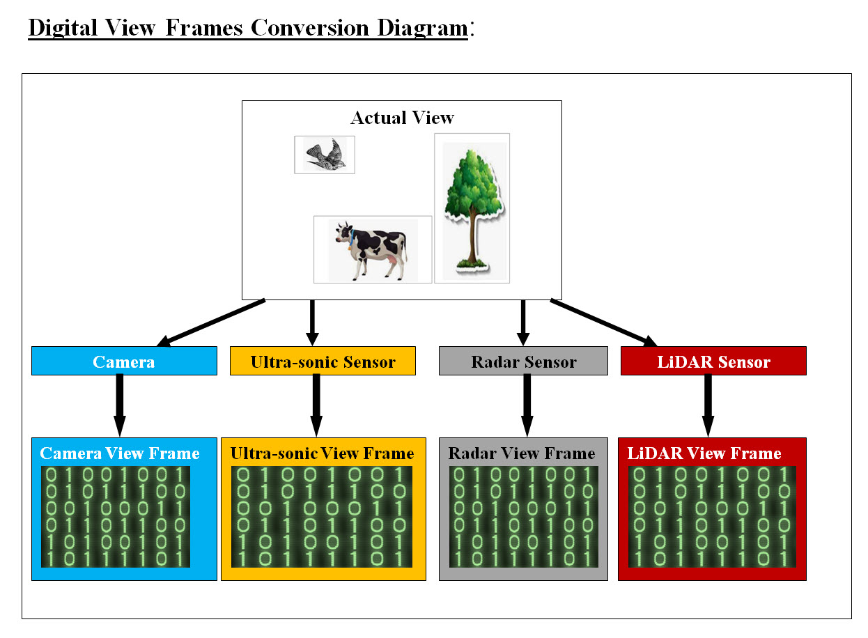
Image #14 Image #14 is showing a rough presentation of how each sensor would convert its data into a digital frame or an array of bytes for analysis which would unify the AV's sensors' analysis. Camera View Frame Data Analysis: We are using Camera View Frame Analysis as the basic structure and processes which we would be used to implement other AV sensors. We are presenting our approach and we are also open to any modification and corrections. The following are some facts which we need to address in our analysis:
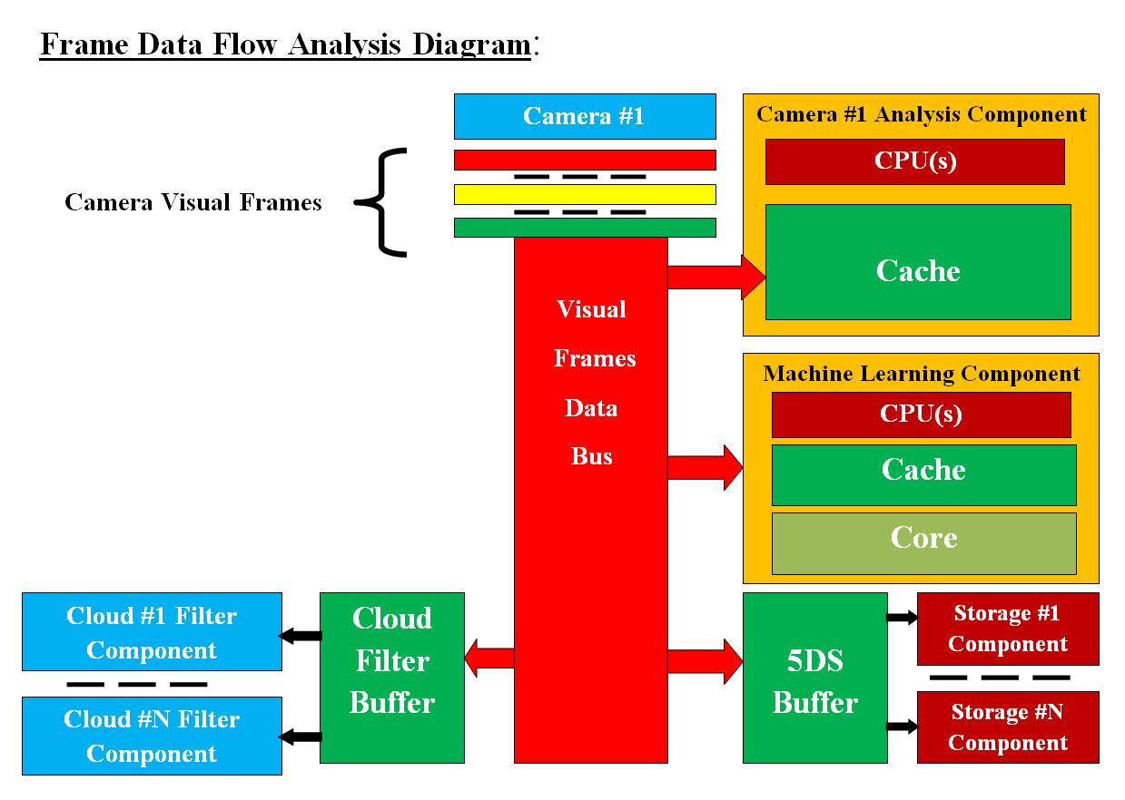
Image #15 We are proposing that each camera would have its own hardware or virtual server to perform the View Frame Data processing. We are also proposing the View Frame data would be sent to the following: 1. Camera #X Analysis Component 2. Machine Learning Component 3. 5DS Buffer 4. Cloud Filter Buffer 5. Storage Component 6. Cloud Filter Component Image #15 is showing the following: • Data Bus which is big enough to handle the size and speed of incoming camera View Frame data • Camera processing hardware or virtual server with all it can use Cache memory and its own processors (CPUs) • Machine Learning virtual server with all it can use Cache and core memory • AV local Data storage (5DS) buffer to accommodate the camera View Frame data • The number of independent Storage Components to handle the Buffer income data • Cloud Filter Components Buffer to accommodate the camera View Frame data • The number of independent Cloud Filter Components to handle the Buffer income data Camera #X Analysis Component Data Flow: From Camera to View Frame data bytes to Data Bus to Camera Analysis Component Cache Memory. Frame Verse Sub-Frame Analysis We need to mention there is distinction been processing View Frame and Sub-Frame. We divided a View Frame into Sub-Frame so our analysis would start at the Sub-Frame which is critical to make a decision or avoid a collision. Once a Sub-Frame has the potential of collision is found, then no future analysis need to start the collision prevention processes. As for analyzing View Frame, the analysis of the entire View Frame is required by the Machine Learning, tracking and storage. The key issue here is the analysis speed, we have a total of two seconds to recognize or figure what our View Frames have which our AV would be able to make a decision plus perform the required prevention processes. Therefore we recommend that any Camera Analysis Component must have independent dedicated CPU or processors and Cache memory to work with. There is No Time to Waist. The Data Bus would be dumping View Frame data or bytes straight into the Cache for processing. We are open to any modification or corrections to our recommendation and nothing is set in stone yet. Our attempt here is to turn the guessing game of what can be found on the road which would cause a possible crash into Objects we know and Objects we do not know. Objects we know: One analysis would be the possible objects we know which can be found on the road. For example in our Image #14, the known objects are caws, trees, or flying birds. We would recommend that one independent core processor with Cache to perform such a task. We do need to work with software vendors who build object recognition software. Bit Vector Search For Objects We Know: What is bit vector comparison? A bit array (also known as bit map, bit set, bit string, or bit vector) is an array stores bits. A bit Vector is effective at bit-level comparison in hardware to perform extremely fast operations. 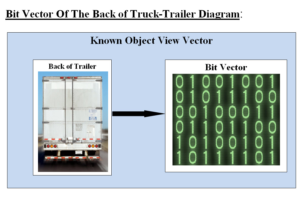
Image #16 Image #16 presents our illustration of how we can have known objects such as the back of trailer stored as a bit vector for fast analysis at hardware level. Objects we do not know: The second type of analysis is countering objects which we do not know and how can we make decisions based on the such analysis. We would recommend that one independent core processor with Cache to perform such a task. Our View of Camera Analysis Component Bare-Metal Structure: 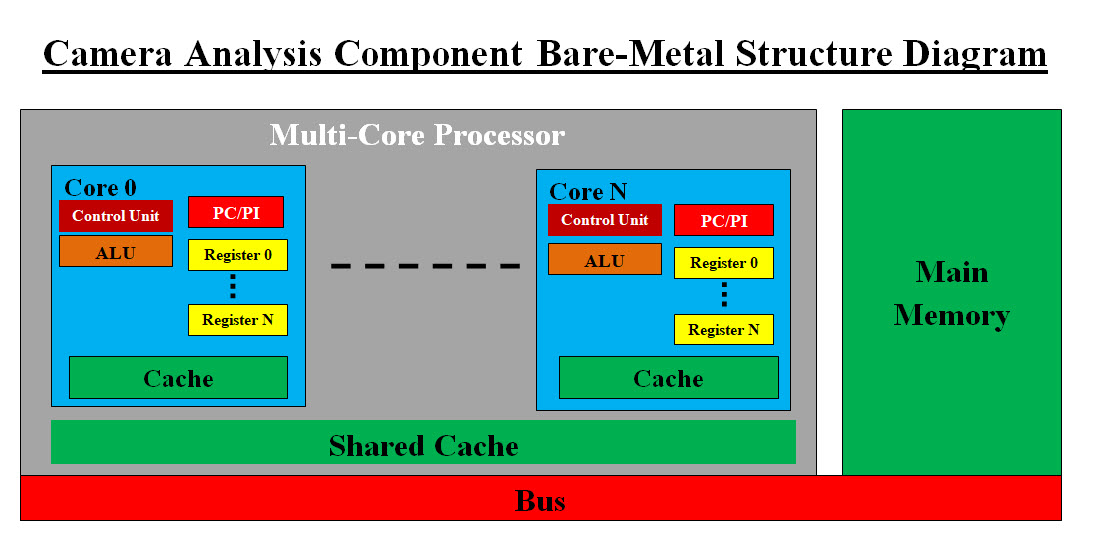
Image #17 Image #17 presents our recommendation where we have more than one dedicated processor performing one analysis option such as Objects we do not know. Performance Speed: We choose bare-metal system with 8 or more processors, all the core memory the server would have. Each processor would have its own Cache, registers and its own virtual server. Each processor would run independently. We hope that we our recommendation is not dated and there could be more advance bare-metal system than what we are presenting. What factors would be considered in bare-metal structure and its performance? CPU, core, clock speed, registers, cache memory, core memory, bus, chip manufacture support, software support, VM, labor, time, testing and cost. Vertical and Horizontal Core Processing: Vertical Core Processing: Our Vertical Core Processing would be done by providing fast analysis with adequate fast core processors and more Cache and core memories. Instruction Set, Cycles Per Instruction, and Clock Cycle Time: We are NOT experts on CPU level speed optimization, but CPU speed can also be part of the Vertical Core Processing. We need to work with the experts and see how can we brainstorm Core Processing speed. This would help in programming the View Frame Analysis. Horizontal Core Processing: Our Horizontal Core Processing would be done by having multiple independent processing unit available to give us more options in processing different things. Machine Learning Component AV Data Flow and Machine Learning (ML): We would be only covering the Data Flow in this section and see Machine Learning View for more details. Data Flow: From Camera to View Frame data bytes to Data Bus to Machine Learning Component. Our Machine Learning Component can be a bare-metal server or virtual servers. The CPUs or processors are critical is analysis speed. Quick Review of Our view of Machine Learning Concept: Our view of Machine Learning is that ML is a backend supportive system to help with decision-making, security and constantly and continuously adds more knowledge and providing more options. For example, Machine Learning for a tomato store, would be the support software that helps in the decision-making about everyday processes. ML also would be able to provide information about the store customers. ML would let the store owner or the salesperson know that the customer they are dealing with is either a shoplifter or a window shopper based on the customer purchasing history. ML also let them know that another customer has 90% chance of buying 15 pound of tomato based in this customer's purchasing history. ML would help with the store protections. AV Main Objectives: • Running AV the way human run their vehicles • Secure AV components and part from hacking and theft • Help with the decision-making • Using history in the decision-making • Adding more knowledge to its knowledge base • Copy AV running data to the cloud for further analysis Storage Component AV sensors produce a lot of data which must be analyzed and stored. We are recommending the sensors data must be filtered and compressed before such data would be stored. This would help in saving storage space and faster processing. For example, Camera View Frames may have several View Frame with identical byte content, or with hardly in change in the byte content. Therefore, we may store the first frame as is, but the next identical frame(s) or with the difference between the frames is minimal would be the only data stored. We would create the difference as Delta Changes. Each frame would have a timestamp and difference or Delta Changes would also have a timestamp. Frame ID: Horizontal and vertical dimensions of each frame, in pixels Using one byte to store pixel color (256 colors) Frame size in pixels 1920 X 1080 X 1 byte = 2,073,600 byte + the timestamp 1280 X 720 X 1 byte = 921,600 bytes + the timestamp Delta Changes Zero (no change) = Frame ID + timestamp Delta Changes 600 X 300 X 1 byte = 180,000 bytes + Frame ID + timestamp What we recommended would save data and speed the processing. Both the comparison and compression processing speed would be a lot slower the what the Data Bus is supplying, therefore buffering would be required. We would have more than one Storage Components running in parallel. 5DS Buffer Buffers are used to help balance between the different speed of two more devices. For example, CPU speed are far more faster than disk storage device, therefore buffers are used to balance between CPU and disk storage device. 5DS Buffer would be used to accommodate the different in speed between the Data Bus and Storage Component. Cloud Filter Component At this point in the analysis and architecting, the Cloud Filter Component has the same job as the Storage Component. This is a redundancy which we recommend. We also may have a set of different tasks as we learn more on how AV and Cloud are communicating. Cloud Filter Buffer At this point in the analysis and architecting, the Cloud Filter Buffer has the same job as the 5DS Buffer. This is a redundancy which we recommend. We also may have a set of different tasks as we learn more on how AV and Cloud are communicating. Producers and Consumers Balance Management GPS and sensors data as well as other AV components are the data producers and AV analysis components are the data consumers. We need to run have Producers and Consumers Balance Management system, to make sure there is no overloading on one AV component. Such management system must be tested. Processes View What is the best definition of a process? A process is a series of Actions which are carried out in order to achieve a particular result. We would to restate AV Main Objectives: • Running AV the way human run their vehicles • Secure AV components and part from hacking and theft • Help with the decision-making • Using history in the decision-making • Adding more knowledge to its knowledge base • Copy AV running data to the cloud for further analysis We also need create a key phrase as Follows: "We may have a total of 2 seconds to handle any road situation" Our view AV processing is divided into the following categories: • Single Process - Single Task • Parallel Processing • The number of lines of code which would be executed in parallel • CPU - Core Speed Single Process - Single Task: • Each AV Process is an application (programming code) • The time it would take to execute or run one (average) AV process • The total number of all possible AV processes which would be ready to run independently Parallel Processing: • The advantages of parallel processing are that applications can be execute code more efficiently and save time • Parallel processing can also solve more complex problems, bringing more resources • Solve Larger Problems in a short point of time • The disadvantage is its complexity of programming and its algorithms The number of lines of code which would be executed in parallel: • The number of processes which would be executed in parallel could be in the millions line of code • Divide and Conquer Concept must be used CPU - Core Speed: • CPU speed required to execute an AV process for top performance • Using multiple core processors would increase the available computation power for faster application processing • Parallel computing saves time, allowing the execution of applications in a shorter wall-clock time AV Processes or tasks are Nemours and complex, we need to present our Processes Flow in the following AV Task example - Changing Lanes Processes. We hope such example can shade some light on our AV Processes Flow. AV Task Example - Changing Lanes Processes: For our AV changing lanes on the road to be a success, we need to mimic human thinking. A professional driver has enough experience to handle any situation based on the driver's past experience. Thoughts of what to do would be running in the driver's brain which would lead to the driver's reaction or action to handle the situation.
Our architect views AV Processes as the actions needed to achieve AV's Main Objectives. We are categorizing AV processes into level of processes. For example, if our AV needs to change lanes, then there are the following Level Process to perform such a task: 1. Sensors Level Processes 2. Communication Level Processes 3. Control Unit Level Processes 4. Machine Learning Level Processes 5. Decision Level Processes 6. Pre-Execution Level Processes 7. Execution Level Processes 8. Post-Execution Level Processes We need to remind the world that we only have less than "Two Seconds" to perform Level Processes 1-7. As for Post-Execution Level Processes is more of get back to level One - Sensors Level Processes. Therefore, each of the AV Processes must be: • Preset - packaged ready for action or execution • We must know exactly how long (Millisecond = 0.001 second or less) each process would take • Each Process is pretested - no guessing • Processes sequences and end of job must be done with precision Practice Run - Change Lanes Series of Processes: Our goal is that AV would perform the lane change similar to what a professional driver would do. The "Two Second" restraint is what AV has to work with. What is an Action? An Action is the performance of a number of tasks to attain an objective. One Action may perform one or more tasks. For example, "Check with Sensor" Action may require that all the sensors processes must start and give their feedback for the decision-making process. The following are what we view as the Actions needed for AV Changing Lane: 1. Sensors - Object found = slow moving vehicle 2. Communicate to Control Unit 3. Check all sensors feedback 4. Decision = need to change lane 5. Machine Learning feedback on decision 6. Safety check points = is changing lane doable? 7. Machine Learning - Action Approved 8. Start "Timer" Process - check time required to perform Actions "Load Object + Move vehicle + Misc" 9. If Timer replay "not enough time" and start at Action #2 10. If Timer = enough time to perform the needed Actions 11. Decision = start the change lane processes 12. Loading Objects into Buffers 13. Move vehicle into target lane 14. Possible issues which could be started ( example the slaw vehicle moved into the target lane) 15. If Changing lane has issues, then alternative processes, and start at Action #2 16. If no issues then proceed to end of processes 17. End of processes 18. Safety checks 19. Proceed back to the normal 20. Machine Learning updates on the Actions taken plus Time feedback Parallel Processing We just a listed 20 Actions needed for AV Changing Lanes and each Action may need one or more task to run. Which of these tasks would be running in parallel and which would be running in sequence, plus the total time these tasks would take to be executed. Software - Application-Program (code) of AV Processes: Each of the AV processes is nothing but a software process or an application-program (code) which would be stored on the AV Data and Storage (5DS). These processes or applications would have to be called to action. The following are the steps for running theses processes or applications: • Identified which process is needed • Loaded or fetched in core or Cache memory • CPU- processor would start executing "process or an application-program (code)" • The mechanical actions (giving signal, and steering) would be started by the processes software code • Sensors' checking for issues Performance Questions: How many processes AV would be using? Which ones often used based on the type of road and its condition? Which would be tracking all objects on the road? Which would be using history - experience to make decision? Which ones would be memory-resident programs (have the ability to stay in the computer's memory after execution and to continuously run)? Which ones would buffered for faster load into Cache and execution? What else we need to do? Change Lane Practice Run would give us the sense that all the needed processes and decision-making must be preset and ready to be executed with provisions for possible changes. 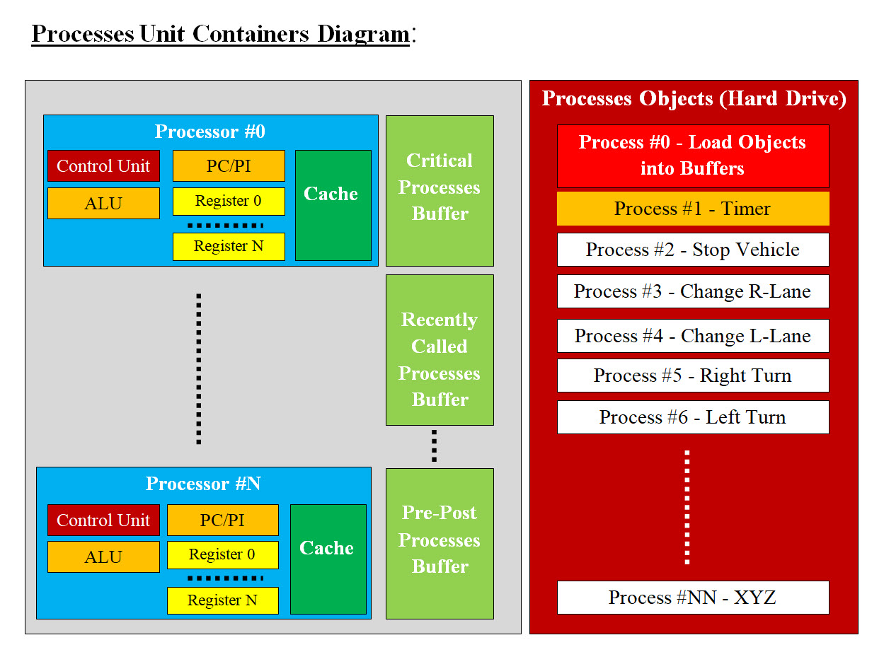
Image #18 Image #18 presents our recommendation of how the hardware (bare-metal) and software-processes would be stored, loaded and run within our two second restraint. Parallel Processing - Revisited: Again which processes would be running in parallel and which would be running in sequence, plus the total time these tasks would take to be executed. We do need to brainstorm our recommendation with other teams including the hardware manufacturing with the following points: • All Processes-Application Objects would stored on the Processes Object Hard drive • The needed buffers would be categorized and set to handle • Recently used processes - the chance of being reused based on history • Pre and post processes which would be required to run a specific process • Set processes • Each buffer would be used to speed the Cache loading for faster execution • The total time of all these processes running must be less than two seconds • Misc. Time View What is Time View? It is critical that we see both AV Components' performance and Processes' execution in time. Therefore, Time View is the processes' execution in time. With the Two Second Constraint we can use Time View to see that we are performing within the Two Second Constraint. For our AV to be a success, AV must be able to process all the possible options. These possible option can be in the thousand of things (cow ,cars, pedestrians, ..etc) we know and tens of thousands of what we do ne know (falling rocks, running water on the road, floods, .. etc). Therefore the number of processing options can be in the tens of thousands. There must be a system or systems running in parallel which would select the best possible options in a sorted fashion. The choices must be narrowed to a smaller number of options to be executed. All these options must be pretested. Once they pass the testing, then they would stored. Their loading and executions most be done in a very short time (millisecond, or less), No guessing. Plus there must be a Timer processing which would calculate the total time required for these processes to run. The Timer would be able to determine if the required performed Actions have enough time to be successfully executed or take alternative Actions which are safer and shorted in time For faster processing we need understand that we have tens of thousands of processes or applications be executed and performed in: • In parallel • Pre • Post • Memory resident • Sequential • Buffered • Rollback • End of job Note: The following tables are more of possible brainstorm runs of some of the AV components and their execution in time. The Millisecond (msec) is more rough presentation of time. The actual time would be a lot less than what we are illustrating with. 1. Sensors - Action Note: Sensors are constantly running
2. Control Unit Action Note: Control Unit is the management system and the decision-maker. Control Unit communicates with and executes processes in sequence and parallel.
3. Objects Loaders - Action Note: Loaders are most likely memory residents.
4. Machine Learning - Action Note: Machine Learning is constantly running in the background for communicating, giving options, help with the decision-making, adding to the new learning, updating cloud, and misc.
Cloud View What is cloud computing? Cloud computing is the delivery of computing services including servers, storage, networking, software, over the Internet. We as architects no longer think except in cloud. Cloud also includes mobile Apps services and the security associated with these services. Note: • Any network with HTTP server or an internet server is a cloud. • Cloud Infrastructure is the base for DevOps and DevOps is the foundation for any Cloud system. What Can the Cloud Do for Autonomous Vehicle? Facts: 1) AV is not running in a vacuum, but AV could be running in heavy traffic such as downtown rush-hour, traffic jammed two ways highway, a highway with heavy construction or rerouted traffic. 2) AV sensors are limited to AV surrounding or views and that can be a handicap for AV. 3) AV size and computing capabilities and storage are also limiting factors. 4) Our Machine Learning is architected to use history and previous experiences for decision-making 5) The number of possible issues or encounters an AV would be facing is overwhelming and the added computing support is critical to AV. 6) Cloud is = servers, storage, networking, software, DevOps, DataOps, old system (legacy), GoldenGate and Data Centers over the Internet. Our AV Cloud View Questions are: • Can the cloud be an added eyes and ears to AV? • Can AVs be part of an Umbrella of clouds? • How to use cloud as an added computing services? • How to secure AV from the cloud? • How to secure the cloud from AV? • Can we treat AV as a mobile or moving Data Center? • Can we treat AV as a mobile or moving Edge Computing Box? To cover all these questions we need to cover a lot of material and the issues attached with them. Therefore, we would be giving a brief answers with examples. Can the cloud be an added eyes and ears to AV? Cloud has options which is too long to cover at this point, but we would be listing what we believe are critical as follows: • A cloud system would probably be supporting thousands of AVs • A cloud system would communicate with AVs and such data cloud be shared • Cloud also have navigation capacities • Cloud has Hugh storage capacities • Cloud could monitor weathers and anything which directly or indirectly impacts AVs • Cloud could have current and history views or data of the roads and what are happing on these roads • Cloud could communicate with states and local authorities and upload the latest data • Cloud could continuously monitor AV and AV status, location, ..etc. • .. etc We can simply conclude that cloud can be the an added eyes and ears to any running AV. Can AVs be part of an Umbrella of clouds? AVs locations and where they would be heading definitely requires constant cloud support. Having an Umbrella of a number cloud seems to be not an option but a must. Such cloud support needs to be secured and protected internally and externally of each member of the cloud Umbrella. The cost associated with such support need to be addressed also. How to use cloud as an added computing services? Definitely cloud is an added computing power or services, but issues such as security, latencies, data sharing, cost, ..etc must be addressed. How to secure AV from the cloud? How to secure the cloud from AV? These topics would be covered in Security View Section. Can we treat AV as a mobile or moving Data Center? Can we treat AV as a mobile or moving Edge Computing Box? These topics would be covered in our Virtual Edge Computing with Machine Learning. In our Virtual Edge Computing webpage, to us, a fully autonomous vehicle can be considered another Data Center which is driving around. See the following link: Sam's Virtual Edge Computing with Machine Learning Security View - for All Cybersecurity Systems (AV Included) Personal Note: We as human have built a number mental and physical processes and tools to protect ourselves and our families and properties. When it comes to AV, can we borrow from our human handling of security? We also need to make it difficult for hackers and thieves to succeed. Thieves or hackers can be governments, big businesses, or well funded organizations. Therefore security is a serious business. How serious AV security could be? AV could be a car, a semi truck (weighing over 80,000 pound) or any service or construction vehicle. If hackeders or thieves would have controll of these vehicles, they could use them to seal or as weapons which would have devastating damages or consequences. What are The Scale, the Size and Challenge of the Task at Hand? What are the scale and the size of our automated intelligent Cybersecurity would be handling? The scale and the size of all the possible item (software of hardware) would be in the hundreds of millions. Let us looking at the following number and do the math. FYI: - Searching the internet: How many bare-metal server an average data Center would have? How many virtual server a bare-metal server may run? How many an average Virtual server may run virtual applications? An average data Center would have about 100,000 bare-metal server. Based on the business requirement a bare-metal server may have between 7 to 64 Virtual server - Virtual Machine. Based on the resources an average Virtual server would run between 8 to 32 Virtual Applications. Let us work the math: 100,000 Server * (7 to 64 Virtual Server) * (8 to 32 Virtual Applications) Low number of virtual applications = 5,600,000 Virtual Application High number of virtual application = 204,800,000 Virtual Application Each bare-metal server would have between 65 to 2,048 Virtual Application Number of Hardware would be over one million: Data center hardware would have servers and computing equipment, networking equipment and storage equipment, plus additional infrastructure to support it like power, cooling systems, ..etc. Physical Monitoring Verse Automation-Intelligence? Looking at the possible number of running application is around 204,800,000 Virtual Application. The hardware would be over one million. It is almost impossible to manually monitor or track 208,000,000 Virtual Application and hardware. Therefore, we do not have a choice but to automate and tracking 208,000,000 Virtual Application and hardware. Is automation doable? Our Analysis and architect is our answer to the automation of All Cybersecurity Systems. Securing AV: Our first question when it comes to securing AV would be: What are we securing? We are securing data, hardware, software, communication, processes, the vehicle parts and/or anything AV would be using. In short, anything which would impact AV continuous running. The number of items to be secured would be equal all AV components (hardware, software). Therefore, our security must have a strategy of how to handle securing these number of items. Our Strategy: Our Strategy of securing AV is "Divide and Conquer" using Automation and Intelligence. We need start by dividing AV components into: 1. Logical Units -Data, Signals, Software-applications, OS, virtual servers, virtual components, virtual devices 2. Physical Units - automotive parts, bar-metal servers, sensors, NAS, Hard drives, Cache, Buffers, The Logical Unites can be in the thousands - every software including OS and Hypervisors, virtual servers, ..etc. The Physical Unit can be few thousands - every physical part which can be damaged, stolen or tampered with. Automation and Intelligence: what is automation? Searching the internet, we found: The dictionary defines automation as “the technique of making an apparatus, a process, or a system operate automatically.” Our view of automation is building a system which would perform the target tasks without any human help or interfaces. For example, automating Cybersecurity detection is to create detection software which would perform Cybersecurity detection without any human help. Such an automated detection can be scheduled to run on scheduled basis or on demand. Intelligence: Intelligence is the automation biggest asset, where Intelligence would eliminate redundancies, correct errors and improve automation performance. To achieve automation and intelligence, we need turn almost everything we are automating into numbers or digits so computer software can work with, analyze, track, draw conclusions, audit trail, find patterns, ..etc. Also processing numbers are far more faster to perform. How can we automat security and make it intelligent? We need to work with numbers, therefore, we need to turn almost all of AV components, status and functionalities into numbers and store these numbers into matrices: 1. IDs (Component ID, security ID, task ID, session ID, ..etc) 2. Functionalities 3. Status 4. Performance 5. Tracking 6. Misc Matrices: We need matrices to store these numbers for processing, tracking, history, comparison, ..etc. The key ingredient is building these number so both human and machine would be understand and use. For example, a Camera component ID would be created and used in the software a Constant as follows: CAMERA_NO_1_ID = 1001560782; // 1001 for cameras, 560 for location rear, 782 for functionality It would be stored in the matrix as 1001560782 for ID. Human and Numbers: Human or IT professional would have issues working the only numbers, therefore, our matrices must have names and descriptions, notes and anything which can making these matrices comprehensible, otherwise our jobs as IT professionals would very difficult. The Number of AV Logical Unites and Physical Unit and Their ID: Physical Unit (PU): If you consider large parts such as the engine as one part, you can say that a car has about 1,800 separate parts. The engine alone has thousands of individual parts inside it. We can also add all sensors then the total would be around 2,000 parts. Physical Unit (PU) ID:
Physical Unit ID Table is more a rough draft for creating AV Physical Component ID Matrices so both human and computer can analyze with ease. Logical Units(LU): Logical Units would include all the system software, applications, security software, Machine Learning software, data files and all cloud communication software, which would be in the thousands. Each of these logical units must be known plus its functionality. Since all AV processes must be tested, timed (how long it would take to perform its tasks) and stored and ready to be loaded into Cache for execution.
Logical Unit ID Table is more a rough draft for creating AV Logical Component (software including OS) ID Matrices so both human and computer can analyze with ease. Software Size in Kbyte: We need to remind that hackers would able to add their malicious code any place (middle, append to the end, ..etc) in an application. By identifying the size of the application in Kbyte our software detection can use the size of a known application to check if any malicious code has been added. Also hackers may name their malicious applications with the names of a known applications. Size of a running application could be used to raise a red flag. Software Execution Time: We need software execution time for the following reasons: Detection Red Flag: The same software size concept can be used for a the time a running application. If an application is taking more time than it should, this also can be used to raise a red flag. Calculation of Total Execution Time: Calculation of total execution time of all the required applications to perform their tasks is required for 2 second restriction. AV Component Status Type? AV vulnerability plus the unpredictable events which AV could encounter are numerous. We believe security would be responsible for keeping AV running uninterrupted. AV security is critical and literately each AV component hardware, software or even the car parts can be totally or partially have one or more of the following Status Type:
The Status Table #3 is more of rough draft of what possible issues AV Security may run into. Each Error or issue must have an integer ID for fast processing. Some Component may not be application (NA) for one of the Status Type. For example, AV car part would have "ID - NA" for Status Type ID for "Has Bug" Status Type. "NA" would actually be a number but we would be displaying in matrices as NA. Our Goal of Automation: To achieve AV security automation, we need to create software tools to perform the following Prevention and Remedy:
Each of the Prevention and the Remedy processes must be automated and constantly checking each of AV component status. Therefore each of AV component must have a system of identification for both human (analysts) and software performing the Prevention and Remedy processes. What would the Physical Unit (PU) Status Table (Matrix) and the Logical Units(LU) Status Table (Matrix) look like? Both human and computer software would be looking What would the Physical Unit (PU) Status Table (Matrix) and the Logical Units(LU) Status Table (Matrix) we are presenting. These tables are rough draft and the actual tables would be a lot bigger with more data (IDS, Descriptions, Notes, ..etc)
Table #4 Cameras' Physical Unit (PU) Status Table (Matrix) is showing that the cameras number 1 and 3 were stolen. Camera # 4 was tampered with but it is still functioning. Camera # 2 was not touched. Note: Every status must have name and ID number presenting the status name for faster processing. For example, any status ID is => equal or greater than 009000, then we are dealing with theft.
Table #5 Logical Units(LU) Status Table is showing running processes in the personal Windows system. The following are applications or programs running on my Windows laptop: Registry Snagit32.exe AP ABC dasHost.exe Quick Review: To summarizes what we need to in steps: IDs: • Create an ID for each Logical and physical items running in the Data Center • Static-Known IDs - would be know and static such as OS Util example Windows Registry • Dynamic IDs - would be dynamic where clients would be running their own customized applications • Static IDs - Physical (bare-metal) servers • Dynamic IDs - virtual servers • Dynamic IDs for virtual devices such as virtual routers or virtual firewalls • Static IDs - Create ID for each functionality of each Logical and physical items running • Dynamic IDs Create ID for each functionality of each dynamic created items Dynamic Creation: • How can we create Static IDs on the run? • How can we create Dynamic IDs on the run? • How can we create functionalities for IDs on the run? To make our goal of creating all the dynamic and static ID and functionalities, let us present the following two scenarios: New Laptop: When I bought my laptop, it came with a number of CDs with all Windows files, therefore, we do have all the names of every static ID for system software. As for the functionalities, the name of these files can help with figuring out the functionalities. Loading my HTML personal pages, Java servlets and Java code on my hosted site: In this scenario, I have to use my host tools or FileZilla unities software to upload all my files (page and Java Code). Again we do have names and sizes of each of the files loaded on the server. As for the functionalities, the name of these files can help with figuring out the functionalities or we would be making educated guesses on the names, but we do have the size. We can see that we do have almost all the names and sizes of each logical item on the network or the entire Data Center, but we need to build software tools to automate our tasks or these tools may already exist and in use. Let us give an short example of what we are presenting. Let us say we have the following three items on AV (with the assumption that Windows OS is running in AV): • Registry = one of the Windows software which would be running • Snagit32.exe = a Windows screen Capture utility • Rear Left Tire on AV For us to track these three items and see the data in the rows of the Tracking Table #6 (Matrix):
Tracking Table #6 presents rows of data about each item. The data presented in the Tracking Table #6 are showing what is going on with each item. Both Human and Machine would be able to analyze the data in the Tracking Table #6 and can make a conclusion and decisions. How Can We Populate Our Tracking Matrices? The following sections "Prevention and Remedy" would present the matrices population processes. Our Intelligent Automated Cybersecurity Prevention and Remedy Our Cybersecurity approach to Prevention and Remedy for all (Autonomous Vehicle, Data Centers or cloud systems). Image #19 presents Our Intelligent Automated Cybersecurity Prevention and Remedy Components which is composed of: • Scanning, Detecting and Remedy All Incoming Traffic to a Running Cloud • Scanning, Tracking, Detecting and Remedy All the Software and the Hardware Running on the Cloud System(s) • Push-Pull and Remedy Internal and Remote Software All Our Intelligent Automated Cybersecurity components are built to run independently without any human interface and would create matrices of data about the running cloud and remote servers. These matrices would be analyzed to tracked, audited trail and evaluated and make intelligent decisions to secure all the cloud hardware and software. 
Image #19 Image #19 presents our Cybersecurity approach where all incoming traffic, internal system and remote servers can be checked for issues automatically or on scheduled basis. These Cybersecurity components populate Cybersecurity Matrices for our Cybersecurity Engines to perform their security tasks. Plus tracking, audit trail and logging would be used to help with the prevention and Machine Learning tools. Scanning, Detecting and Remedy All Incoming Traffic to a Running Cloud We are using our approach to Machine Learning Scanning, Detecting and Remedy See the following link for details: Sam's Machine Learning Analysis, Data Structure-Architect In a nutshell, every byte coming into our cloud is guilty until proven innocent. Our View of Networks' Detection Issues: 
Image #20 Looking at Image #20, all the OSI seven layers or TCP/IP five layers can be hacked. Our main concern in this page is the packet's data. All the internet inbound traffic (digital) is composed of streams of bytes and any stream could be a possible carrier of hackers' code. How can we build speedy a detection with flexibility to tackle any variation? Our Machine Learning Detection Components are: Our architect-design has robust components for continuous scanning. In the case of our scanning encounters a difficult, time consuming or a new case, the scanning would be moved a Dedicated Virtual Testing Server to handle the issues separately. Our Crashes rollback is nothing more than moving the production IP address to the Virtual Rollback Server. 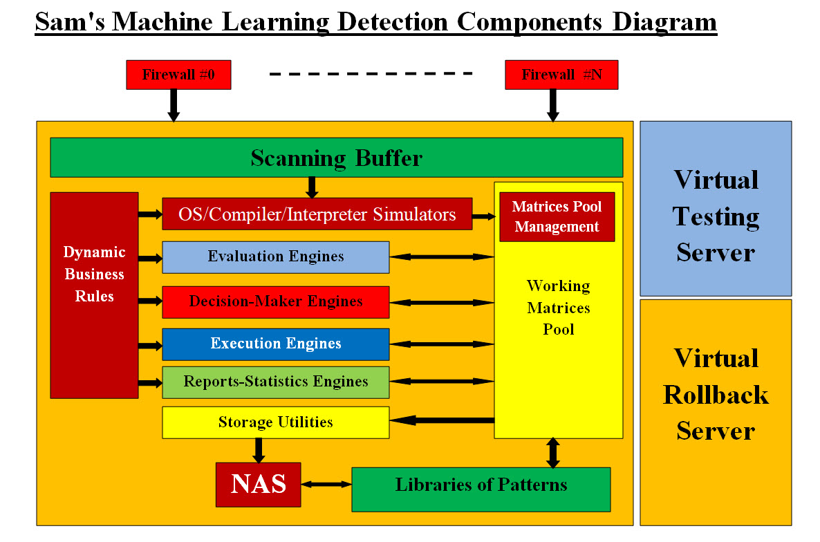
Image #21 Looking at the Image #21, we have three virtual servers or subsystems. The 2,000 foot view of our ML has the following major subsystems:
Machine Learning (ML) Components - Image #21: 1. Scanning Buffer(s) 2. OS and Compiler-Interpreter Simulators 3. Libraries of Patterns 4. Dynamic Business Rules 5. Sort Engines 6. Tracking Engines 7. Operation Matrices - Matrices Working Pool 8. Matrices Pool Management 9. Evaluation Engines 10. Decision-Maker Engines 11. Execution Engines 12. Reports-Statistics Engines 13. Storage Utilities 14. Storage - NAS 15. Virtual Testing Server 16. Virtual Rollback Sever How can we build an intelligent system? In a nutshell, the following steps or processes are what defines "Human Intelligence" which is the ability to: 1. Learn from experience - (Zeros-&-Ones to develop the Bytes, Words and the Scanning Patterns) 2. Adapt to new situations - (Scanning and tracking) 3. Understand and handle abstract concepts - (Matrices for tracking and processing) 4. Use knowledge to manipulate one's environment - (Engines to run the system) Our Remedy Approach: We need to address Remedy based on the running applications and no one size fits all. Scanning, Tracking, Detecting and Remedy All the Internal Software and the Hardware Our Remedy and Scanning Approaches: Remedy:- we need to address Remedy based on the running applications and no size fit all. Scanning:- we would be using our Machine Learning approach. Hardware Tracking: We would need help with hardware tracking based on type and functionalities of each of the hardware and the devices. Software Tracking: Remember our Math in counting the number items running in a Data Center: 100,000 Server * (7 to 64 Virtual Server) * (8 to 32 Virtual Applications) Low number of virtual applications = 5,600,000 Virtual Application High number of virtual application = 204,800,000 Virtual Application Each bare-metal server would have between 65 to 2,048 Virtual Application Our Matrices Tree: Top Tree Matrix = 100 Groups (clusters) of bare-metal server One group Server Matrix = 1,000 bare-metal server One Bare-metal Server Matrix would have = 64 Virtual Server One Virtual Server Matrix would have = 2,048 Virtual Application Every application would a record of data Every Record would have a unique ID We are working with about 208 million record, which would require automation. Our Questions would be: How would we build five level of nesting matrices? How can these matrices be populated with the proper data? How to automate populating these matrices? First, we need to work the Data Center managers and their software tools. The matrices structure would have 5 level of matrices and every level would have a record of fields structure and within its fields structure, one field would be a matrix of the next lower level of matrices.
Table #7 - Matrices Structure Table presents the matrices data structure and we need to use Java, C-C++, scripts (Unix or Linux, Windows) to retrieve data about all the elements in Table #7. Automated Tracking and Monitoring: Our goal is automating Internal Tracking and Monitoring using software. Image #22 presents our architect of how would we be using the Operating System calls to populate a shared buffer(s) and save the data to a hard drive plus NAS for permanent storage for later analysis and evaluations. Image #22 has two sections: • Clients Cloud System • Our Cybersecurity Tracking System Image #22 Clients Cloud System: Clients Cloud System presents a number running virtual servers with all their internal virtual Operation System and virtual applications. One of the virtual application is our Tracking Application which we will present our sample Java code for it later in this section. Each virtual server presents one of the possible scenarios of VM#1 - a normal run, VM#2 - a hacked virtual application and VM#Z - the Operating system could possibly been hacked. The key is that our Virtual Tracking Application would make a call to the OS which the OS is running inside this virtual server. This insures that the data we are collecting is accurate and current for every running virtual server. Our Tracking Application would be receiving a stream of data about all the running virtual applications including the Operating System as follows: Windows - running the following Java code on my personal laptop - using NetBeans: try { System.out.println("Processes Reading is started..."); //Get Runtime environment of System runTime = Runtime.getRuntime(); //Execute command thru Runtime localProcess = runTime.exec("tasklist"); // For Windows //Create Inputstream for Read Processes InputStream inputStream = localProcess.getInputStream(); InputStreamReader inputStreamReader = new InputStreamReader(inputStream); BufferedReader bufferedReader = new BufferedReader(inputStreamReader); String line = bufferedReader.readLine(); int lineCount = 1; System.out.println(lineCount + ")" + line); while (line != null) { lineCount++; line = bufferedReader.readLine(); System.out.println(lineCount + ")" + line); } Print out: run: Processes Reading is started...
The output or the print out is showing the details about each running software (Image Name, PID, Session Name, Session#, and Mem Usage) and how many were running on personal laptop (205). Linux - "ps aux" Code: The ps aux command is a great tool to monitor processes running on your Linux system. It can be used to get any running program’s memory usage, processor time, and I/O resources. Tracking Application: So far, what we presented (in the code above) is how our Tracking Application would call the OS (Windows or Linux) and be able collect all the data about every running software including OS. Plus each virtual server would be called separately. There is no confusion about which virtual server has what software is running within it. Our Cybersecurity Tracking System: Our Cybersecurity Tracking System would be running in its own virtual server. There would be only system running with Management, Matrices Management, buffer(s), hard drive + NAS and as many instances of Engines as needed to handle the load. Our architect has the following components: • Management System • Matrices Management • Shared Buffer(s) • Hard drive and NAS • Engines • Tracking Engine • Analysis Engine • Decision-Maker Engine • Execution Engine • Reporting Engine • Scheduling Engine • Audit Trail Engine • Remedy Engine • Push-Pull Engine • Updates Engine Our Management System for Our Internal Cybersecurity Tracking System: Task at Hand: What is the Data Center Security Tracking Specifications? 1. Data Center may have 100,000 bare-metal Server 2. Number of items running is 208 Million software and hardware 3. Each Item has one record of all the data needed data for security tracking, audit trial and running information 4. The size of each record must be small = string of IDs (Comma Separated Value CSV) record 5. Processing speed = using numbers or Digits for IDs, size, functionalities, ..etc 6. Automating data collection in building the record 7. Use any existing world standard to create the data record or create a new one 8. All data must be shared using shared buffers, files, memory resident software or data structures, matrices 9. Develop secured sharing and access structure types for sharing data among bare-metals, virtual servers, local and remote servers 10. Processes = pipes, write to files, application calls, Push-Pull 11. Permanent storage on hard drives and NAS 12. On Demand or scheduled data population processes 13. Testing 14. Cross reference with any existing security monitoring The number of items (software and hardware) is about 208 millions, therefore automation, the performance speed, accuracy and control or the management are critical. We are using a number of software engines which would be performing all the detailed tasks. Engines are virtual applications and their number is created dynamic based on the needed tasks. These engines share data matrices where the data is created dynamically on the run. We are architecting a management system which it would be controlling the lifecycle each of these engines from cradle to grave and their communication. Our Machine Learning software tools runs a number of management and matrices control. We used Analysis, Decision-Makers and Execution Engines to perform management system. Matrices Management: Matrices are spinal cord of our Internal Cybersecurity system. We use matrices to share data on the run, where engines would be consuming the data in the these matrices. One matrix may be shared between different engines and synchronization of the needed engines is controlled be the Our Management System. These matrices are also stored on the hard drive and/or the NAS. Shared Buffer(s): Buffering is critical for speed and the use of different types and sizes records. We do need help with developing buffers which would address all the data sharing issues. Hard drive and NAS: Hard drive and NA are used as permanent storage and as well as buffering devices. Engines: What is an Engine? What is a Process? Based on Information Technologies background, an engine may have different meanings. Our Engine Definition: • An Engine is a running software (application, class, OS call) which performs one task and only one task. • A Process is a running software which uses one or more engine. A Process may perform one or more task. • Engines are used for building loose coupled system and transparencies • Updating one engines may not require updating any code in the system • A tree of running engines can be developed to perform multiple of tasks in a required sequence • Engines give options and diversities Table of Engines: Possible: more than one engine for the same functionality. A this point in analysis, design and architecting stages, we may need to modify a lot items including engines. Therefore, there could be more than one engine performing the same task based on different use cases or scenarios. For example, Remedy may require more than one type of Remedy.
We are also open for any corrections, suggestions, critics, or recommendations. Push-Pull and Remedy Internal and Remote Software What is Push-Pull? What is push pull in programming? Pull coding or client pull is a style of network communication where the initial request for data originates from the client, and then is responded to by the server. The reverse is known as push technology, where the server pushes data to clients. Electronic Circuit Push-Pull: A push–pull amplifier is a type of electronic circuit that uses a pair of active devices that alternately supply current to, or absorb current from, a connected load. This kind of amplifier can enhance both the load capacity and switching speed. 1.Push :- connector requests devices for their logs 2. Pull:- devices themselves sends logs to connector server Why do we need Push-Pull in our Cybersecurity system? Our answer would: Why Cybersecurity uses Cookies? What are the advantages using Cookies? In a nutshell, a Cookie is a limited size string of characters (4096 bytes) which is passed back and forth between users and servers for security, communication, setups and other customization features. Can we use the Cookies Concept to pass back and forth between Cybersecurity-Detection software tools and running applications? Our Push-Pull Approach is using a limited size string of characters (4096 bytes) which is passed back and forth between Cybersecurity-Detection software tools and running applications. Our Push-Pull Cookies Strategies: Our objective is to start dialogs between running applications and Cybersecurity software tools. Such dialog can be used to know the running applications status and eliminate hacking applications from running in the memory of virtual servers. Plus Push-Pull Cookies can be used start remote dialogs between our Cybersecurity software tools and remote servers and their running applications. Note: This would require new way of coding cloud applications. New applications have to develop the Push method and the Pull method. This would start a new standards of coding and libraries of Application Programming Interface (API). Our Push-Pull Cookies (Request and Response): Push-Pull (request and response) can use the following options: • Function call • OS call • Script call • Signals exchange • Other reply based on the item being Pulled example pulse or electric current • Hard Disk - The FAT (short for File Allocation Table) file system Developing these Push-Pull (request and response) would require special coding in all AV applications, shell scripting, OS call functions (possible C programming), batch code, hypervisor, kernel, and device drivers (which are written in C language). Note - Hypervisor: A hypervisor, also known as a virtual machine monitor or VMM, is software that creates and runs virtual machines (VMs). A hypervisor allows one host computer to support multiple guest VMs by virtually sharing its resources, such as memory and processing. Devices Push-Pull: We need help with the hardware devices since software is our specialty and not the hardware. The data created for the Push-Pull calls would be stored in matrices, which we would be using in our security automation. Such matrices would be used in cross reference with other matrices to be able to detect errors, malfunction, or hacking. These matrices would be also used in audit trail and tracking. Push-Pull Cookie Structure: We recommend the following string structure for • Component Type • Component ID • Timestamp • Status The following is Security Push Method example code in Java ================================================================ 47 /** 48 * Security Push Method example code 49 */ 50 public static int securityCookiePush (String inputCookie) 51 { 52 System.out.println("==== securityCookie Push method started ======== class="string">"); 53 System.out.println("inputCookie - timestamp Long = " + inputCookie); 54 55 // code for security checks 56 57 System.out.println("==== End securityCookie Push method ======== class="string">"); 58 59 return(0); 60 } 61 /** 62 * Security Push Method example code 63 */ 64 public static String securityCookiePull(String inputCookieString) 65 { 66 System.out.println("==== securityCookie Pull method started ========"); 67 long timestampLong = Calendar.getInstance().getTimeInMillis(); 68 String localtimestampLongString = "" + timestampLong; 69 70 String securityCookiePullString = ""; 71 String securityCookiePushTimestampString = inputCookieString; 72 String securityCookiePullID_String = "ID"; 73 String securityCookiePullComponentType = "Type"; 74 String securityCookiePullComponentID = "Component"; 75 String securityCookiePullStatus = "Status"; 76 77 securityCookiePullString = "" 78 + securityCookiePushTimestampString + "," 79 + localtimestampLongString + "," 80 + securityCookiePullID_String + "," 81 + securityCookiePullComponentType + "," 82 + securityCookiePullComponentID + "," 83 + securityCookiePullStatus; 84 85 System.out.println("==== End securityCookie Pull method ========"); 86 return(securityCookiePullString); 87 } 88 /** 89 * 90 */ 91 public static void main (String[] args) 92 { 93 System.out.println("===== Main start ===================== class="string">"); 94 95 long timestampLong = Calendar.getInstance().getTimeInMillis(); 96 String inputCookieString = "" + timestampLong; 97 int result = securityCookiePush(inputCookieString); 98 String localSecurityCookiePullString = securityCookiePull(inputCookieString); 99 100 System.out.println("=========================="); 101 System.out.println("inputCookie - timestamp Long = " + inputCookieString); 102 System.out.println("localSecurityCookiePullString = " + localSecurityCookiePullString); 103 104 System.out.println("=========================="); 105 } 106 107 } run: ===== Main start ===================== ==== securityCookie Push method started ======== inputCookie - timestamp Long = 1668126200946 ==== End securityCookie Push method ======== ==== securityCookie Pull method started ======== ==== End securityCookie Pull method ======== ========================== inputCookie - timestamp Long = 1668126200946 localSecurityCookiePullString = 1668126200946,1668126200980,ID,Type,Component,Status ========================== BUILD SUCCESSFUL (total time: 0 seconds) ++++++++++++++++++++++++++++++++++++++++++++++++++++++++++++++++++++++ Remote Push-Pull Cookie API Calls: Application Programming Interface (API) Definition: An application programming interface, or API, gives companies the options to communicate with to external third-party developers and business partners, or to departments within their companies. API leverages data exchange and services and communicate with other products and services. Using Push-Pull Cookies as API gives our Cybersecurity software tools an additional options to track-audit trail remote applications Machine Learning View The goal is to present how our Machine Learning (ML) would running in the background as the supporting decision-making. Please note this is the second time we are representing the link to our Sam's Machine Learning Analysis, Data Structure-Architect link as follows: Sam's Machine Learning Analysis, Data Structure-Architect Our ML is composed of: • Our Running Supportive Software Tools • Our Offline Analysis Note: There is a difference between tracking and ML support. Our Cybersecurity system is architect to track 208 million virtual running application and the hardware running. ML support is a customized system with a specific goal. The number of virtual applications running within a Data Center can be 208 million. The number of the ML support can get out of hand and would be difficult to manage, therefore, clients need to prioritize which running application would have to have ML support, which would be nice to have and which would be a batch processing. Running Supportive ML Software Tools: Our Running Supportive ML software tools run 24X7 and it is customized to each running application. It provides the Execution Matrix for the running application to use as an option to handle the tasks at hand. For example, in case of detecting a malicious code or a hackers application, ML will supply the running application a list of execution remedy processes. Each execution process comes with Weight-Score Value (example 87%) of how effective the process would be if is executed in eliminating the malicious code or the hackers application. This gives the running application an option to choose between its own remedy process or ML remedy process. Our Offline Analysis: Our Offline Analysis is the analysis and developing of any new cases the system encountered which our ML is aware off. In short it is a factor for building new tools and cases in supporting our ML. It also tracks and archives all the running cases our ML performing. 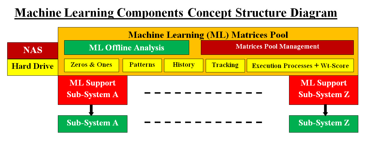
Image #23 Image #23 is our Machine Learning Components Concept Structure Diagram, where each sub-system or a running application would have its own dedicated ML Supporting System or tools. For more details see Sam's Machine Learning Analysis, Data Structure-Architect Page. Analysis-Decision-Execution Engines and Machine Learning Support 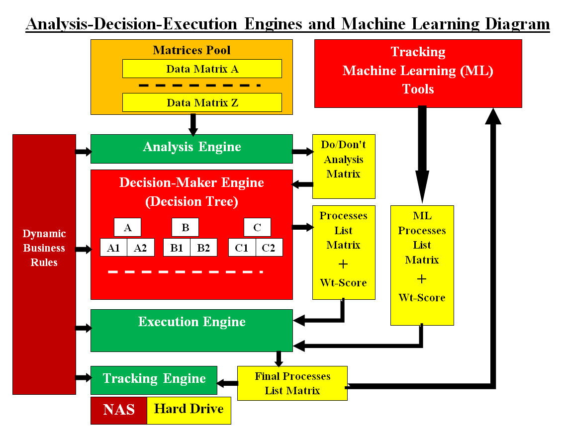
Image #24 Our architect of how any of our running system (including detection-remedy) and our ML tools interface to handle the Decision-making and Execution of final processes. In a nutshell, our Analysis, Decision-Maker use the matrices and produces Processes List Matrix with Weight-Score Values. The Execution Engine would use both Processes List Matrix with Weight-Score Values and ML Processes List Matrix with Weight-Score Values and decides on which processes would be inserted in the Final Processes Matrix for execution. Image #24 Image #24 presents the engines, matrices, and ML interfaces. Matrices Pool: Matrices Pool is a collection of almost all the data needed by all the engines to run or produce for other engines to use. If we do an analogy of how important our Matrices is, we would state the our Matrices Pool is the spine of our intelligent system. They are the connections between all the processing, learning, tracking, analysis, updating, storage, audit trail and misc. Matrices Pool Management is critical to their performance. Tracking Machine Learning (ML) Tools: This is a dedicated ML software tool(s) customized to help with the decision-making. It provides ML Processes List Matrix with Weight-Score. Analysis Engine: The main task of Analysis Engine is to prepare "Do/Don's Analysis Matrix". Such matrix is used by Decision-Maker Engine to traverse the decision tree and create a list processes to be executed by the Execution Engine. "Do/Don's Analysis Matrix". Do/Don't Analysis Matrix: " Do/Don't" is more of a generic name for a matrix with options which is prepared by the Analysis Engines. Such matrix would be named according the running application job description. Decision-Maker Engine (Decision Tree): Once the Analysis Engine or the Tracking Engine is done with its tasks, the Decision-Maker Engine would access the matrices for conditions, rules and based on the preset rules, it would be performing its tasks. similar to decision-making in human. Decision-Maker would traverse the Decision Tree to create "Do/Don's Analysis Matrix". ML Processes List Matrix + Wt-Score: This matrix will be provided by the ML software tool(s). It has a list of processes and their Weight-Score Values as an added decision options. Processes List Matrix + Wt-Score: This matrix will be provided by the ML software tool(s). It has a list of processes and their Weight-Score Values as an added decision options. Execution Engine: Execution Engine would be using Processes List Matrix with Wt-Score values and ML Processes List Matrix with Wt-Score values. It will be choosing processes based on Weight-Score Values to develop the Final Processes List Matrix to be executed. Final Processes List Matrix It is a list of the final processes which would be executed. Tracking Engine: It is used in Tracking users, software and machines. Dynamic Business Rules: Dynamic Business Rules help in giving guidance on decision-making (if-else conditions). These rules can be added at runtime without the need to change code or processes. Hard Drive and NAS: Hard drive and NA are used as a permanent storage and as well as buffering devices. Using Computer Models and Virtual Testing Computer Models and Virtual Testing are nothing more than tools which are used to build things more efficiently, economically, eliminate errors and costly mistakes. It also speeds up the execution of building things. Actually, such tools can be the decisive factor between a project that is doable or out of reach. Hollywood and moviemakers use "Computer Models and Virtual Testing" to make-believe of things such as the futuristic existence of galaxies, plants, buildings, war equipments and spaceships as shown in the "Star Wars" movies. So our job as analysts is to simplify "Computer Models and Virtual Testing" so the common man would understand and see the benefits of such tools. |
|---|